2. 山西省自动化研究所, 山西 太原 030024
2. Shanxi Institute of Automation, Taiyuan 030024, Shanxi, China
三相电压型PWM整流器(voltage source PWM rectifier, VSR)结构简单, 呈低阻抗的电压源特性, 在可再生能源的并网发电、高压直流输电、统一潮流控制等领域有着广泛应用。三相VSR通常采用双闭环控制结构[1], 传统的电压、电流PI控制[2-3]易于实现, 但由于电流内环的耦合特性, 参数整定较为复杂, 鲁棒性还有待提高。为此, 文献[4]提出了内环滑模解耦控制与外环PI控制相结合的控制方式, 提高了系统的鲁棒性。文献[5]对电流内环控制器的趋近律进行了优化, 加快了系统响应, 减小了输出抖振, 但依然存在趋近律选择困难的问题。为实现电流内环的完全解耦, 减少内环可调参数个数, 文献[6]提出了外环PI控制, 内环内模控制的方法, 设计了集中控制器, 但由于控制器个数多, 参数整定困难。
相比整数阶PID控制器, 分数阶控制器(PIλDμ)[7-9]可以实现更加灵活的控制效果, 使系统获得更好的动态性能和鲁棒性, 因此, 分数阶微积分理论在电力系统控制中的应用已成为研究热点[10-12]。文献[12]设计了功率内环、直流电压外环的控制结构, 将PIλDμ控制器引入外环控制中, 得到了较好的抗干扰特性, 并基于幅值裕度和相位裕度指标整定了可调参数, 但整定方法较为复杂。考虑到IMC仅有一个可调参数, 跟踪和控制性能好, 将其与分数阶控制相结合, 不仅可以克服参数难以整定的缺点, 同时也使系统的控制性能得到了进一步改善[13-16]。
为了实现电流内环的完全解耦, 增强电压外环的抗扰性, 并减少控制器参数整定个数, 本研究提出了电压外环分数阶IMC和电流内环反向解耦[17-19]IMC相结合的控制方法。该方法设计简单, 参数整定方向明确, 仿真结果表明了所提方法的有效性。
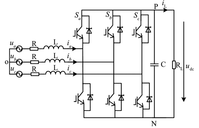
1 PWM整流器的dq数学模型图 1为三相电压型PWM整流器拓扑结构, 其中, ua、ub、uc分别为网侧相电动势瞬时值, ia、ib、ic分别为网侧相电流瞬时值, udc为直流侧母线电压, RL为负载等效电阻, iL为直流母线上的负载电流, S为整流桥的开关函数。
|
图 1 三相电压型PWM整流器拓扑结构 Figure 1 Block diagram of three-phase VSR |
为简化控系统的设计, 通过坐标变换, 可以得到同步旋转坐标系下VSR的电压方程为
| $ \left\{ \begin{array}{l} L\frac{{{\rm{d}}{i_d}}}{{{\rm{d}}t}} = {u_d} - R{i_d} + \omega L{i_q} - {S_d}{u_{{\rm{dc}}}}\\ L\frac{{{\rm{d}}{i_q}}}{{{\rm{d}}t}} = {u_q} - R{i_q} - \omega L{i_d} - {S_q}{u_{{\rm{dc}}}}\\ C\frac{{{\rm{d}}{u_{{\rm{dc}}}}}}{{{\rm{d}}t}} = \frac{3}{2}\left( {{i_d}{S_d} + {i_q}{S_q}} \right) - {i_{\rm{L}}} \end{array} \right., $ |
式中:ud、uq、id、iq分别为两相同步旋转坐标系下, 电网电压、电流矢量在d、q轴的分量; ω为电网电压矢量的旋转角速度; R、L分别为网侧等效电阻及滤波电感和等效漏电感之和; C为直流侧电容; Sd、Sq分别为(d, q)坐标系下的开关函数。为实现网侧有功、无功分量的独立控制, 选取d轴为有功分量参考轴, 若电源相电压最大值为Um, 则ud=Um, uq=0。
令ud1=ud-Sdudc, uq1=uq-Squdc, 则
| $ \left\{ \begin{array}{l} {u_{d1}} = R{i_d} + L\frac{{{\rm{d}}{i_d}}}{{{\rm{d}}t}} - \omega L{i_q}\\ {u_{q1}} = R{i_q} + L\frac{{{\rm{d}}{i_q}}}{{{\rm{d}}t}} + \omega L{i_d} \end{array} \right.。$ |
假设U(s)为整流器的输出电压向量, G(s)为三相电压型PWM整流器传递函数矩阵, Y(s)为电流内环输出(交流侧的输入电流), 则有
| $ \mathit{\boldsymbol{Y}}\left( s \right) = \mathit{\boldsymbol{G}}\left( s \right)\mathit{\boldsymbol{U}}\left( s \right)。$ |
其中,
| $ \mathit{\boldsymbol{U}}\left( s \right) = {\left[ {\begin{array}{*{20}{c}} {{u_{d1}}\left( s \right)}&{{u_{q1}}\left( s \right)} \end{array}} \right]^{\rm{T}}}, $ |
| $ \mathit{\boldsymbol{Y}}\left( s \right) = {\left[ {\begin{array}{*{20}{c}} {{i_d}\left( s \right)}&{{i_q}\left( s \right)} \end{array}} \right]^{\rm{T}}}, $ |
| $ \mathit{\boldsymbol{G}}\left( s \right) = {\left[ {\begin{array}{*{20}{c}} {R + sL}&{ - \omega L}\\ {\omega L}&{R + sL} \end{array}} \right]^{ - 1}} = \left[ {\begin{array}{*{20}{c}} {{g_{11}}}&{{g_{12}}}\\ {{g_{21}}}&{{g_{22}}} \end{array}} \right]。$ |
考虑到三相VSR的耦合特性, 基于反向解耦原理, 设计了反向解耦器, 使电流内环实现了完全解耦, 再根据解耦后的各个单回路分别设计内模控制器, 实现了各个回路的单独控制。
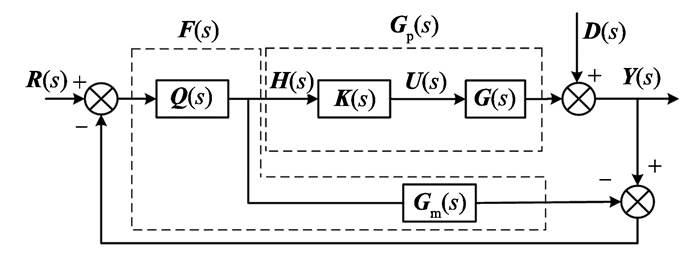
图 2为电流内环反向解耦内模控制结构框图, G(s)为被控对象, K(s)为反向解耦器, Gp(s)为解耦后的广义被控对象, Gm(s)为Gp(s)的模型, Q(s)为内模控制器, H(s)为IMC控制器的输出, F(s)、R(s)和D(s)分别为等效控制器、电流给定和干扰信号, 其中
| $ \mathit{\boldsymbol{R}}\left( s \right) = {\left[ {\begin{array}{*{20}{c}} {i_d^ * \left( s \right)}&{i_q^ * \left( s \right)} \end{array}} \right]^{\rm{T}}}, $ |
|
图 2 反向解耦内模控制结构框图 Figure 2 Block diagram of inverted decoupling IMC |
式中:id*(s)、iq*(s)分别为id、iq的电流指令。
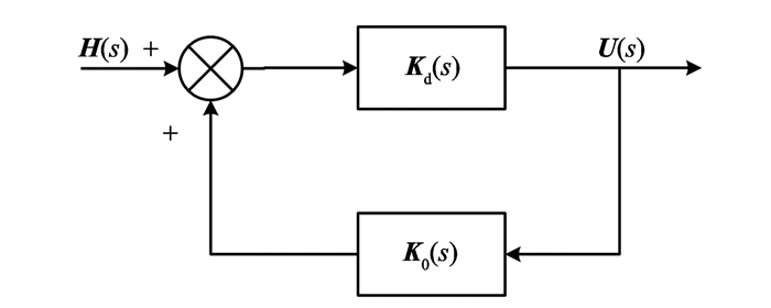
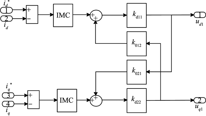
2.2 反向解耦器的设计如图 3所示, 反向解耦器K(s)由Kd(s)和K0(s)组成, 其中Kd(s)为前向通道传递函数矩阵, K0(s)为正反馈通道传递函数矩阵。
|
图 3 K(s)结构图 Figure 3 Block diagram of K(s) |
K(s)应使解耦后的模型为期望的对角矩阵, 即G(s)K(s)=Gp(s), 当Gp(s)可逆时, 有
| $ {\mathit{\boldsymbol{K}}^{ - 1}}\left( s \right) = \mathit{\boldsymbol{G}}_{\rm{p}}^{ - 1}\left( s \right)\mathit{\boldsymbol{G}}\left( s \right)。$ | (1) |
令解耦后的广义矩阵
| $ {\mathit{\boldsymbol{G}}_{\rm{p}}}\left( s \right) = {\rm{diag}}\left( {\frac{1}{{R + sL}},\frac{1}{{R + sL}}} \right) = {\rm{diag}}\left( {{p_1},{p_2}} \right)。$ | (2) |
由图 3可得
| $ \mathit{\boldsymbol{K}}\left( s \right) = {\mathit{\boldsymbol{K}}_{\rm{d}}}\left( s \right){\left[ {\mathit{\boldsymbol{I}} - {\mathit{\boldsymbol{K}}_0}\left( s \right){\mathit{\boldsymbol{K}}_{\rm{d}}}\left( s \right)} \right]^{ - 1}}, $ | (3) |
对式(3)求逆, 则
| $ {\mathit{\boldsymbol{K}}^{ - 1}}\left( s \right) = \mathit{\boldsymbol{K}}_{\rm{d}}^{ - 1}\left( s \right) - {\mathit{\boldsymbol{K}}_0}\left( s \right)。$ | (4) |
联立式(1)和(4), 得
| $ \mathit{\boldsymbol{K}}_{\rm{d}}^{ - 1}\left( s \right) - {\mathit{\boldsymbol{K}}_0}\left( s \right) = \mathit{\boldsymbol{G}}_{\rm{p}}^{ - 1}\left( s \right)\mathit{\boldsymbol{G}}\left( s \right), $ |
则有
| $ {k_{{\rm{d11}}}} = \frac{{{p_1}}}{{{g_{11}}}}\frac{{{{\left( {R + sL} \right)}^2} + {{\left( {\omega L} \right)}^2}}}{{{{\left( {R + sL} \right)}^2}}}, $ |
| $ {k_{{\rm{d22}}}} = \frac{{{p_2}}}{{{g_{22}}}}\frac{{{{\left( {R + sL} \right)}^2} + {{\left( {\omega L} \right)}^2}}}{{{{\left( {R + sL} \right)}^2}}}, $ |
| $ {k_{012}} = - \frac{{{g_{12}}}}{{{p_1}}} = - \frac{{\omega L \cdot \left( {R + sL} \right)}}{{{{\left( {R + sL} \right)}^2} + {{\left( {\omega L} \right)}^2}}}, $ |
| $ {k_{021}} = - \frac{{{g_{21}}}}{{{p_2}}} = \frac{{\omega L \cdot \left( {R + sL} \right)}}{{{{\left( {R + sL} \right)}^2} + {{\left( {\omega L} \right)}^2}}}, $ |
因此
| $ {\mathit{\boldsymbol{K}}_{\rm{d}}}\left( s \right) = \left[ {\begin{array}{*{20}{c}} {\frac{{{{\left( {R + sL} \right)}^2} + {{\left( {\omega L} \right)}^2}}}{{{{\left( {R + sL} \right)}^2}}}}&0\\ 0&{\frac{{{{\left( {R + sL} \right)}^2} + {{\left( {\omega L} \right)}^2}}}{{{{\left( {R + sL} \right)}^2}}}} \end{array}} \right], $ |
| $ {\mathit{\boldsymbol{K}}_0}\left( s \right) = \left[ {\begin{array}{*{20}{c}} 0&{\frac{{\omega L \cdot \left( {R + sL} \right)}}{{{{\left( {R + sL} \right)}^2} + {{\left( {\omega L} \right)}^2}}}}\\ { - \frac{{\omega L \cdot \left( {R + sL} \right)}}{{{{\left( {R + sL} \right)}^2} + {{\left( {\omega L} \right)}^2}}}}&0 \end{array}} \right]。$ |
相对于常用的解耦方法, 反向解耦矩阵K(s)设计简单, 实现了标称系统的完全解耦, 且解耦后的表达式形式有更多的灵活性, 进而便于各个单回路分别设计控制器[19]。
2.3 电流环内模控制器的设计由式(2)知, 解耦后电流内环的被控对象Gp(s)是对角矩阵, 且主对角线元素为相同的一阶传递函数, 可设低通滤波器fci(s)的形式为
| $ {\mathit{\boldsymbol{f}}_{{\rm{ci}}}}\left( s \right) = \frac{\lambda }{{s + \lambda }}\mathit{\boldsymbol{I}}, $ |
式中:λ为电流环滤波器参数; I为单位阵。
模型精确时, 即Gm(s)=Gp(s), 根据内模控制原理设计内模控制器
| $ \mathit{\boldsymbol{Q}}\left( s \right) = \mathit{\boldsymbol{G}}_{\rm{m}}^{ - 1}\left( s \right){\mathit{\boldsymbol{f}}_{{\rm{ci}}}}\left( s \right), $ |
则电流内环等效控制器为
| $ \mathit{\boldsymbol{F}}\left( s \right) = {\left[ {\mathit{\boldsymbol{I}} - \mathit{\boldsymbol{Q}}\left( s \right){\mathit{\boldsymbol{G}}_{\rm{m}}}\left( s \right)} \right]^{ - 1}}\mathit{\boldsymbol{Q}}\left( s \right) = \lambda \left[ {\begin{array}{*{20}{c}} {L + R/s}&0\\ 0&{L + R/s} \end{array}} \right]。$ |
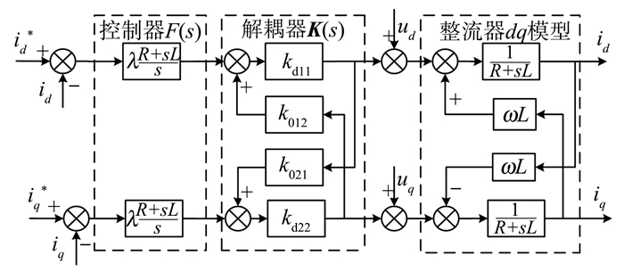
图 4为电流内环反向解耦内模控制结构框图, 可见只需要2个完全相同的控制器, 且仅有一个可调参数。
|
图 4 基于反向解耦的内模控制框图 Figure 4 Block diagram of IMC based on inverted decoupling |
在标称情况下, 电流内环的闭环传递函数矩阵
| $ \mathit{\boldsymbol{L}}\left( s \right) = \frac{{\mathit{\boldsymbol{Y}}\left( s \right)}}{{\mathit{\boldsymbol{R}}\left( s \right)}} = \frac{{\mathit{\boldsymbol{F}}\left( s \right){\mathit{\boldsymbol{G}}_{\rm{p}}}\left( s \right)}}{{\mathit{\boldsymbol{I}} + \mathit{\boldsymbol{F}}\left( s \right){\mathit{\boldsymbol{G}}_{\rm{p}}}\left( s \right)}} = \frac{\lambda }{{s + \lambda }}\mathit{\boldsymbol{I}}。$ | (5) |
由式(5)可知电流内环的闭环传递函数只与滤波器fci(s)的参数有关, 而与被控对象的参数无关, 且λ越大, 电流内环的跟随性越好。
3 电压外环分数阶内模控制器的设计 3.1 电压外环控制结构图 5为简化的电压外环系统框图[20], 其中, Tv为惯性时间常数, Wci(s)为电流环的闭环传递函数, 0.75mcosθ表示考虑开关函数基波分量的直流侧电流, m为PWM的调制比。

|
图 5 电压外环系统框图 Figure 5 Block diagram of voltage outer loop system |
由式(5)可得
| $ {W_{{\rm{ci}}}}\left( s \right) = \frac{\lambda }{{s + \lambda }} = \frac{1}{{s/\lambda + 1}}。$ |
为简化控制结构, 令m cos θ=1, 并将Tv与1/λ合并, 即T=Tv+1/λ, 则电压外环被控对象的传递函数
| $ P\left( s \right) = \frac{{0.75}}{{Cs\left( {1 + Ts} \right)}} = \frac{K}{{s\left( {1 + Ts} \right)}}, $ | (6) |
式中K=0.75/C。
选择分数阶滤波器
| $ {f_{{\rm{cu}}}}\left( s \right) = \frac{1}{{1 + \eta {s^\gamma }}}, $ |
式中:η为电压环滤波器参数; γ为滤波器的分数阶阶次, 且1 < γ < 2。
内模控制器
| $ {C_{{\rm{IMC}}}}\left( s \right) = {M^{ - 1}}\left( s \right){f_{{\rm{cu}}}}\left( s \right) = \frac{{s\left( {1 + Ts} \right)}}{{K\left( {\eta {s^\gamma } + 1} \right)}}, $ |
式中M(s)为P(s)的模型。
等效控制器
| $ C\left( s \right) = \frac{T}{{K\eta {s^{\gamma - 2}}}}\left( {1 + \frac{1}{{Ts}}} \right)。$ | (7) |
由式(7)可知设计的分数阶内模控制器仅有η、γ两个可调参数, 本研究采用文献[16]提出的基于截止频率和最大灵敏度Ms指标的参数整定方法。
由式(6)和(7)得到电压外环开环传递函数
| $ L\left( s \right) = C\left( s \right)P\left( s \right) = \frac{1}{{\eta {s^\gamma }}}。$ |
根据截止频率[21]的定义得
| $ \left| {L\left( \omega \right)} \right| = \frac{1}{{\eta \omega _{\rm{c}}^\gamma }} = 1, $ | (8) |
式中ωc为开环传递函数L(s)的截止频率。
灵敏度函数的定义为
| $ S\left( s \right) = \frac{1}{{1 + L\left( s \right)}}。$ |
因此, 最大灵敏度
| $ {M_s} = \mathop {\max }\limits_{0 \le \omega < \infty } \left| {S\left( {{\rm{j}}\omega } \right)} \right| = \mathop {\max }\limits_{0 \le \omega < \infty } \left| {\frac{1}{{1 + L\left( {{\rm{j}}\omega } \right)}}} \right|。$ |
当1 < γ < 2时, 灵敏度幅值为
| $ \begin{array}{l} \left| {S\left( {{\rm{j}}\omega } \right)} \right| = \left| {\frac{{\eta {{\left( {{\rm{j}}\omega } \right)}^\gamma }}}{{1 + \eta {{\left( {{\rm{j}}\omega } \right)}^\gamma }}}} \right| = \left| {\frac{{\eta {\omega ^\gamma }{{\rm{e}}^{{\rm{j}}\frac{{\rm{ \mathsf{ π} }}}{2}\gamma }}}}{{1 + \eta {\omega ^\gamma }{{\rm{e}}^{{\rm{j}}\frac{{\rm{ \mathsf{ π} }}}{2}\gamma }}}}} \right| = \\ \;\;\;\;\;\;\;\;\;\;\;\;\;\;\left| {\frac{{\eta {\omega ^\gamma }\left[ {\cos \left( {\frac{{{\rm{ \mathsf{ π} }}\gamma }}{2}} \right) + {\rm{j}}\sin \left( {\frac{{{\rm{ \mathsf{ π} }}\gamma }}{2}} \right)} \right]}}{{1 + \eta {\omega ^\gamma }\left[ {\cos \left( {\frac{{{\rm{ \mathsf{ π} }}\gamma }}{2}} \right) + {\rm{j}}\sin \left( {\frac{{{\rm{ \mathsf{ π} }}\gamma }}{2}} \right)} \right]}}} \right| = \\ \;\;\;\;\;\;\;\;\;\;\;\;\;\;\frac{1}{{\sqrt {1 + \frac{1}{{{{\left( {\eta {\omega ^\gamma }} \right)}^2}}} + \frac{2}{{\eta {\omega ^\gamma }}}\cos \left( {\frac{{{\rm{ \mathsf{ π} }}\gamma }}{2}} \right)} }}。\end{array} $ | (9) |
对式(9)求极值可知, 当
| $ {M_s} = \mathop {\max }\limits_{0 \le \omega < \infty } \left| {S\left( {{\rm{j}}\omega } \right)} \right| = \frac{1}{{\sqrt {1 - {{\cos }^2}\left( {\frac{{{\rm{ \mathsf{ π} }}\gamma }}{2}} \right)} }}。$ | (10) |
由式(8)和(10)可知控制器C(s)的参数为
| $ \left\{ \begin{array}{l} \eta = \frac{1}{{\omega _c^\gamma }}\\ \gamma = \frac{2}{{\rm{ \mathsf{ π} }}}\arccos \left( { - \sqrt {1 - \frac{1}{{M_s^2}}} } \right) \end{array} \right.。$ | (11) |
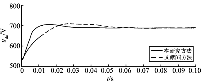
为验证本研究方法的有效性, 在Simulink环境下搭建了系统的仿真模型, 并与文献[6]所提方法进行比较, 图 6、7分别为电压外环和电流内环的控制模块。仿真参数如下[6]:网侧相电压幅值Um=311 V, 整流器输入电阻R=0.15 Ω, 输入电感L=5 mH, 直流侧电容C=1 650 μF(初始电压设定为540 V), 直流侧的负载等效电阻RL=69 Ω, 主电路开关频率fs=4 kHz, 母线电压给定值为690 V。

|
图 6 电压外环控制模块 Figure 6 Simulation model of voltage outer loop |
|
图 7 电流内环控制模块 Figure 7 Simulation model of current inner loop |
为了比较的公平性, 取电流环滤波器参数λ=4 400。为保证电压外环的抗扰性, 根据式(11), 选取Ms=1.8, ωc=250 Hz, 得到η=0.000 12, γ=1.625。
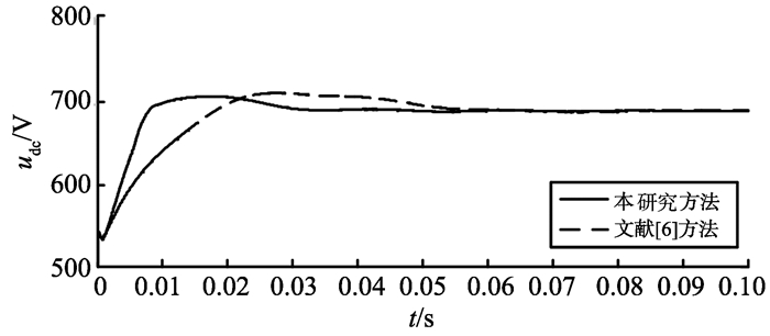
4.1 系统的起动响应图 8为标称情况下直流侧电压波形, 经过约0.032 s后直流侧电压就基本稳定在给定值, 相比较文献[6], 需要更短的稳定时间。为考察系统的鲁棒性, 假定网侧输入电阻产生+20%的摄动, 电感产生+30%的摄动, 即R=0.18 Ω, L=6.5 mH, 仿真波形如图 9所示。表 1给出了两种情况下系统性能指标的比较, 结果表明, 本研究方法有更小的超调量, 更快的起动响应。
|
图 8 标称模型的直流侧电压波形 Figure 8 DC voltage waveforms of normal system |
|
图 9 模型失配的直流侧电压波形 Figure 9 DC voltage waveforms of perturbed system |
| 表 1 控制系统性能指标 Table 1 Performance parameters of control system |
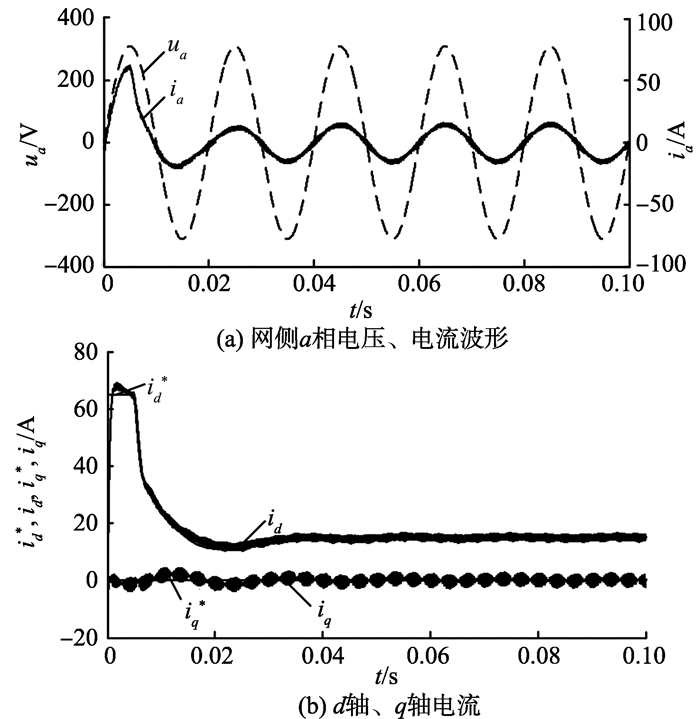
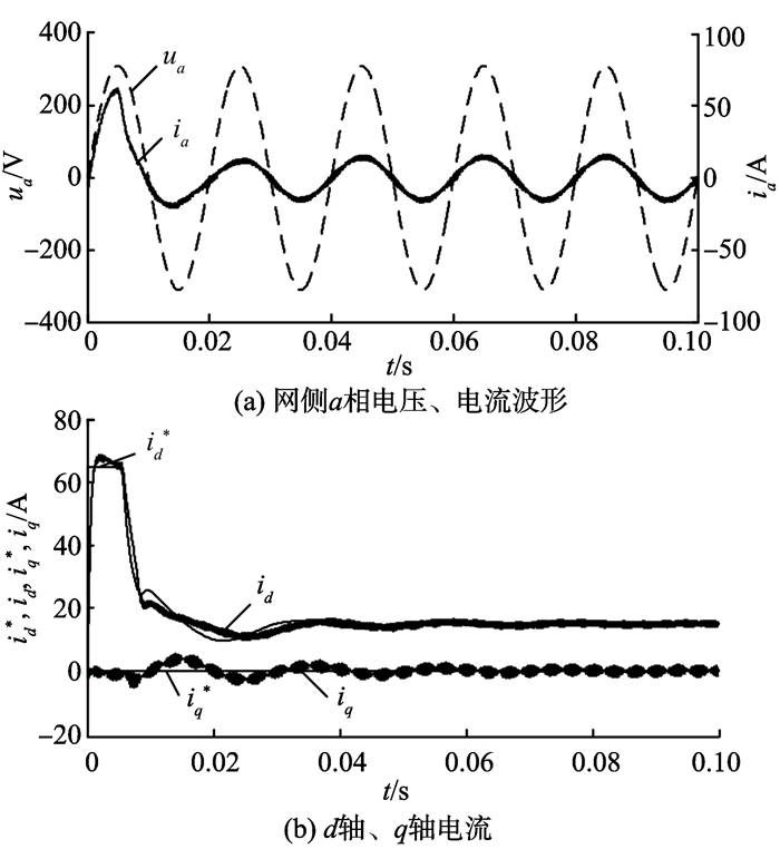
图 10、11分别为标称模型和模型失配情况下, 采用本研究方法的仿真波形。从仿真结果可以看出, 本研究方法在两种情况下网侧电流基本实现了正弦化; 有功电流和无功电流均可完全解耦, 跟随性较好, 并能快速进入稳定状态。
|
图 10 标称模型的稳态仿真波形 Figure 10 Steady-state simulation waveforms of normal system |
|
图 11 模型失配的稳态仿真波形 Figure 11 Steady-state simulation waveforms of perturbed system |
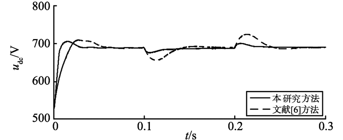
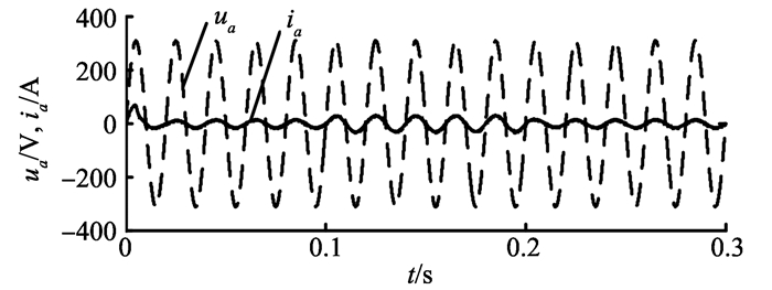
负载发生突变时的仿真波形如图 12、13所示, 仿真状态为:第0.1秒RL由69 Ω突变为138 Ω, 第0.2秒时又突变为69 Ω。图 12为直流侧电压仿真波形对比, 图 13为采用本研究方法的网侧电压、电流波形。系统的控制性能参数比较如表 2所示, 可以看出, 所提方法可获得更稳定的直流母线电压, 有更好的抗扰性, 网侧电流波形基本实现正弦化。
|
图 12 负载突变时直流侧电压波形 Figure 12 DC voltage waveforms under load variation |
|
图 13 负载突变时网侧电压、电流波形 Figure 13 Voltage and current waveforms under load variation |
| 表 2 负载突变时的控制系统性能参数 Table 2 Performance parameters under load variation |
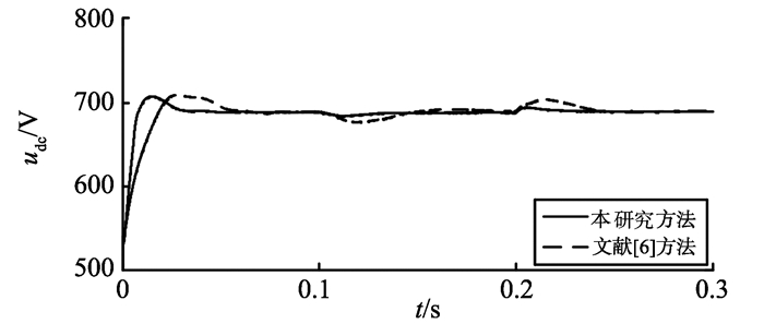
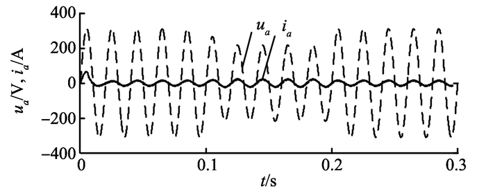
网侧电压摄动时的仿真波形如图 14、15所示, 仿真状态为:第0.1秒电网电压发生30%的跌落, 持续0.1 s, 第0.2 s电网电压恢复正常。图 15为采用本研究方法的网侧电压、电流波形, 仿真结果表明, 当电网电压发生变化时, 网侧电流仍能实现正弦化和单位功率运行。表 3给出了系统的控制性能参数比较, 显然, 本研究所提策略有更快的响应速度, 更小的动态偏差, 鲁棒性优于文献[6]所提的控制方法。
|
图 14 网侧电压变化时的仿真波形图 Figure 14 Simulation waveforms under input voltage variation |
|
图 15 网侧a相电压、电流波形 Figure 15 Voltage and current waveforms |
| 表 3 控制系统性能参数 Table 3 Performance parameters of the control system |
本研究将IMC控制方法应用到三相VSR双闭环控制中去, 结合反向解耦原理和分数阶控制理论, 设计了反向解耦IMC控制器和分数阶IMC控制器; 针对电压外环滤波器参数的整定, 给出了一套具体可行的方法。仿真结果表明, 相对于文献[6]提出的控制方法, 本研究方法的控制器更少, 设计更加灵活, 使系统在负载突变、模型失配和网侧电压突变的情况下具有更好的动态性能。
| [1] |
程启明, 程尹曼, 薛阳, 等. 三相电压源型PWM整流器控制方法的发展综述[J].
电力系统保护与控制, 2012, 40(3): 145-155 CHENG Qiming, CHENG Yinman, XUE Yang, et al. A summary of current control methods for three-phase voltage-source PWM rectifiers[J]. Power System Protection and Control, 2012, 40(3): 145-155 DOI:10.3969/j.issn.1674-3415.2012.03.028 |
| [2] |
汪万伟, 尹华杰, 管霖. 双闭环矢量控制的电压型PWM整流器参数整定[J].
电工技术学报, 2010, 25(2): 67-79 WANG Wanwei, YIN Huajie, GUAN Lin. Parameter setting for double closed-loop vector control of voltage source PWM rectifier[J]. Transactions of China Electrotechnical Society, 2010, 25(2): 67-79 |
| [3] |
王长恺, 尹华杰. 三相电压型PWM整流器的系统设计与PI参数校正[J].
电气传动, 2011, 41(3): 41-45 WANG Changkai, YIN Huajie. System design and PI parameter calibration of three-phase voltage source PWM rectifier[J]. Electric Drive, 2011, 41(3): 41-45 |
| [4] |
唐勇奇, 赵葵银, 汪超. 基于滑模变结构控制的三相PWM整流器[J].
电力自动化设备, 2006, 26(5): 39-41 TANG Yongqi, ZHAO Kuiyin, WANG Chao. Three-phase PWM rectifier based on sliding-mode variable structure control[J]. Electric Power Automation Equipment, 2006, 26(5): 39-41 DOI:10.3969/j.issn.1006-6047.2006.05.010 |
| [5] |
丁祖军, 刘保连, 倪伟. PWM整流器中优化变结构控制策略的设计[J].
电力自动化设备, 2012, 32(1): 76-79 DING Zujun, LIU Baolian, NI Wei. Design of improved variable structure control for PWM rectifier[J]. Electric Power Automation Equipment, 2012, 32(1): 76-79 DOI:10.3969/j.issn.1006-6047.2012.01.015 |
| [6] |
宋文祥, 尹赟. 一种基于内模控制的三相电压型PWM整流器控制方法[J].
电工技术学报, 2012, 27(12): 94-101 SONG Wenxiang, YIN Yun. A control strategy of three-phase PWM rectifier based on internal model control[J]. Transactions of China Electrotechnical Society, 2012, 27(12): 94-101 |
| [7] | PODLUBNY I. Fractional-order systems and PIλDμ controllers[J]. IEEE Transaction on Automatic Control, 1999, 44(1): 208-214 DOI:10.1109/9.739144 |
| [8] |
赵志涛, 赵志诚, 王惠芳. 直流调速系统模糊自整定分数阶内模控制[J].
山东大学学报(工学版), 2015, 45(5): 58-62 ZHAO Zhitao, ZHAO Zhicheng, WANG Huifang. Fractional order internal model control with fuzzy-tuning for DC speed regulating system[J]. Journal of Shandong University (Engineering Science), 2015, 45(5): 58-62 |
| [9] |
赵春娜, 赵雨, 张祥德, 等. 分数阶控制器与整数阶控制器仿真研究[J].
系统仿真学报, 2009, 21(3): 768-775 ZHAO Chunna, ZHAO Yu, ZHANG Xiangde, et al. Simulation research on fractional order controllers with integer order controllers[J]. Journal of System Simulation, 2009, 21(3): 768-775 |
| [10] |
梁祖权, 束洪春. 新型UPQC直流电压的PIλDμ控制[J].
电工技术学报, 2010, 25(2): 147-151 LIANG Zuquan, SHU Hongchun. Novel UPQC DC voltage research of PIλDμ controller[J]. Transactions of China Electrotechnical Society, 2010, 25(2): 147-151 |
| [11] |
李志民, 孙其振, 孙勇, 等. PMSG风力发电系统最大风能追踪的分数阶控制[J].
电力系统及其自动化学报, 2012, 24(6): 67-72 LI Zhimin, SUN Qizhen, SUN Yong, et al. Maximum energy tracking of PMSG wind power generation system by fractional-order control[J]. Proceedings of the CSU-EPSA, 2012, 24(6): 67-72 DOI:10.3969/j.issn.1003-8930.2012.06.013 |
| [12] |
王璇, 张小凤, 周丰, 等. 三相电压型PWM整流器分数阶PID直接功率控制[J].
电气传动, 2013, 43(4): 45-49 WANG Xuan, ZHANG Xiaofeng, ZHOU Feng, et al. Direct power control based on fractional-order PID controller of three-phase voltage source PWM rectifier[J]. Electric Drive, 2013, 43(4): 45-49 DOI:10.3969/j.issn.1001-2095.2013.04.011 |
| [13] | LI D, LIU L, JIN Q, et al. Maximum sensitivity based fractional IMC-PID controller design for non-integer order system with time delay[J]. Journal of Process Control, 2015, 31(7): 17-29 |
| [14] | BETTAYEB M, MANSOURI R. IMC-PID-fractional-order-filter controllers design for integer order systems[J]. ISA Transactions, 2014, 53(5): 1620-1628 DOI:10.1016/j.isatra.2014.05.007 |
| [15] | BETTAYEB M, MANSOURI R. Fractional IMC-PID-filter controllers design for non integer order systems[J]. Journal of Process Control, 2014, 24(4): 261-271 DOI:10.1016/j.jprocont.2014.01.014 |
| [16] |
赵志涛, 赵志诚, 张井岗. 直流位置伺服系统的二自由度分数阶控制[J].
信息与控制, 2016, 45(4): 421-425 ZHAO Zhitao, ZHAO Zhicheng, ZHANG Jinggang. Two-degrees-of-freedom fractional control method for DC position servo system[J]. Information and Control, 2016, 45(4): 421-425 |
| [17] | GARRIDO J, VÁZQUEZ F, MORILLA F. An extended approach of inverted decoupling[J]. Journal of Process Control, 2011, 21(1): 55-68 |
| [18] | SUN L, DONG J, LI D, et al. A practical multivariable control approach based on inverted decoupling and decentralized active disturbance rejection control[J]. Industrial & Engineering Chemistry Research, 2016, 55(7): 847-866 |
| [19] | GARRIDO J, VÁZQUEZ F, MORILLA F, et al. Practical advantages of inverted decoupling[J]. Proceedings of the Institution of Mechanical Engineers Part Ⅰ: Journal of Systems & Control Engineering, 2011, 225(7): 977-992 |
| [20] |
邹学渊, 王京, 张勇军, 等. 基于内模控制的改进型三相PWM整流器[J].
电子技术应用, 2009, 35(8): 76-78 ZOU Xueyuan, WANG Jing, ZHANG Yongjun, et al. Improved three-phase PWM rectifier based on IMC[J]. Application of Electronic Technique, 2009, 35(8): 76-78 DOI:10.3969/j.issn.0258-7998.2009.08.041 |
| [21] |
李晶, 姜久春, 牛利勇, 等. 电动汽车充电机输入阻抗特性分析[J].
北京交通大学学报, 2013, 37(2): 79-84 LI Jing, JIANG Jiuchun, NIU Liyong, et al. Analysis of electric vehicle charger input impedance[J]. Journal of Beijing Jiaotong University, 2013, 37(2): 79-84 DOI:10.3969/j.issn.1673-0291.2013.02.015 |


